I/O Connection
Overview
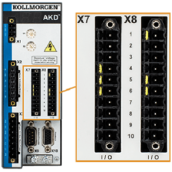
I/O connectors X7 and X8 (all AKD variants)
Standard digital and analog I/O signals are connected to X7 and X8.
|
AKD
|
|---|
|
|
|
Conn. |
Pin |
Signal |
Abbreviation |
Function |
|---|---|---|---|---|
|
X7 |
1 |
Digital Common X7 |
DCOM7 |
Common line for |
|
X7 |
2 |
Digital Input 7 |
DIGITAL-IN 7 |
Programmable |
|
X7 |
3 |
Digital Input 4 |
DIGITAL-IN 4 |
Programmable |
|
X7 |
4 |
Digital Input 3 |
DIGITAL-IN 3 |
Programmable |
|
X7 |
5 |
Digital Output 2- |
DIGITAL-OUT2- |
Programmable |
|
X7 |
6 |
Digital Output 2+ |
DIGITAL-OUT2+ |
Programmable |
|
X7 |
7 |
Digital Output 1- |
DIGITAL-OUT1- |
Programmable |
|
X7 |
8 |
Digital Output 1+ |
DIGITAL-OUT1+ |
Programmable |
|
X7 |
9 |
Digital Input 2 |
DIGITAL-IN 2 |
Programmable,fast |
|
X7 |
10 |
Digital Input 1 |
DIGITAL-IN 1 |
Programmable,fast |
|
|
||||
|
X8 |
1 |
Fault Relay Output |
Fault Relay Output |
Fault Relay Output |
|
X8 |
2 |
Fault Relay Output |
Fault Relay Output |
Fault Relay Output |
|
X8 |
3 |
Digital Common X8 |
DCOM8 |
Common line for |
|
X8 |
4 |
Digital Input 8 |
DIGITAL-IN 8 |
Output stage enable, |
|
X8 |
5 |
Digital Input 6 |
DIGITAL-IN 6 |
Programmable |
|
X8 |
6 |
Digital Input 5 |
DIGITAL-IN 5 |
Programmable |
|
X8 |
7 |
Analog Ground |
AGND |
Analog GND |
|
X8 |
8 |
Analog Output + |
Analog-Out |
Actual velocity voltage |
|
X8 |
9 |
Analog Input - |
Analog-In- |
Velocity set point |
|
X8 |
10 |
Analog Input + |
Analog-In+ |
|
Digital common lines for X7 and X8 are not common to each other.
The DCOMx line should be connected to the 0V of the I/O supply when using sensors of type "Source" with digital inputs.
The DCOMx line should be connected to the 24V of the I/O supply when using sensors of type "Sink" with digital inputs.
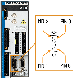
Connector X9 (all AKD variants)
If X9 is not used for second feedback input or EEO, it offers three RS485 channels which are programmable as digital outputs.
|
Conn. |
Pin |
Signal |
Abbreviation |
Function |
|---|---|---|---|---|
|
X9 |
1 |
Digital In/Out 9+ |
Digital-IO 9+ |
Programmable |
|
X9 |
2 |
Digital In/Out 9- |
Digital-IO 9- |
|
|
X9 |
3 |
Digital Common X9 |
DCOM9 |
Reference ground |
|
X9 |
4 |
Digital In/Out 10+ |
Digital-IO 10+ |
Programmable |
|
X9 |
5 |
Digital In/Out 10- |
Digital-IO 10- |
|
|
X9 |
6 |
Shield |
Shield |
Cable shield |
|
X9 |
7 |
Digital In/Out 11+ |
Digital-IO 11+ |
Programmable |
|
X9 |
8 |
Digital In/Out 11- |
Digital-IO 11- |
|
|
X9 |
9 |
reserved |
reserved |
reserved |
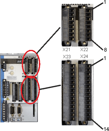
I/O connectors X21, X22, X23 and X24 (AKD-T with I/O option card only)
The I/O option card offers four additional connectors X21, X22, X23, X24 for I/O signals.
|
AKD-xyyyzz-IC |
|---|
|
|
|
Conn. |
Pin |
Signal |
Abbreviation |
Function |
Wiring |
|---|---|---|---|---|---|
|
X21 |
1 |
Digital Input 21 |
DIGITAL-IN 21 |
Programmable |
(see Digital Inputs with I/O option (X21, X22)) |
|
X21 |
2 |
Digital Input 22 |
DIGITAL-IN 22 |
Programmable |
|
|
X21 |
3 |
Digital Input 23 |
DIGITAL-IN 23 |
Programmable |
|
|
X21 |
4 |
Digital Common X21/1_3 |
DCOM21.1_3 |
Common line for |
|
|
X21 |
5 |
Digital Input 24 |
DIGITAL-IN 24 |
Programmable |
|
|
X21 |
6 |
Digital Input 25 |
DIGITAL-IN 25 |
Programmable |
|
|
X21 |
7 |
Digital Input 26 |
DIGITAL-IN 26 |
Programmable |
|
|
X21 |
8 |
Digital Common X21/5_7 |
DCOM21.5_7 |
Common line for |
|
|
|
|||||
|
X22 |
1 |
Digital Input 27 |
DIGITAL-IN 27 |
Programmable |
(see Digital Inputs with I/O option (X21, X22)) |
|
X22 |
2 |
Digital Input 28 |
DIGITAL-IN 28 |
Programmable |
|
|
X22 |
3 |
Digital Input 29 |
DIGITAL-IN 29 |
Programmable |
|
|
X22 |
4 |
Digital Common X22/1_3 |
DCOM22.1_3 |
Common line for |
|
|
X22 |
5 |
Digital Input 30 |
DIGITAL-IN 30 |
Programmable |
|
|
X22 |
6 |
Digital Input 31 |
DIGITAL-IN 31 |
Programmable |
|
|
X22 |
7 |
Digital Input 32 |
DIGITAL-IN 32 |
Programmable |
|
|
X22 |
8 |
Digital Common X22/5_7 |
DCOM22.5_7 |
Common line for |
|
|
Conn. |
Pin |
Signal |
Abbreviation |
Function |
|---|---|---|---|---|
|
X23 |
1 |
Analog Output 2 + |
Analog-Out2 |
Programmable |
|
X23 |
2 |
reserved |
n.c. |
n.c. |
|
X23 |
3 |
Analog Ground |
AGND |
Programmable |
|
X23 |
4 |
reserved |
n.c. |
n.c. |
|
X23 |
5 |
Digital Output 21+ |
DIGITAL-OUT 21+ |
Programmable |
|
X23 |
6 |
Digital Output 21- |
DIGITAL-OUT 21- |
Programmable |
|
X23 |
7 |
Digital Output 22+ |
DIGITAL-OUT 22+ |
Programmable |
|
X23 |
8 |
Digital Output 22- |
DIGITAL-OUT 22- |
Programmable |
|
X23 |
9 |
Digital Output 23+ |
DIGITAL-OUT 23+ |
Programmable |
|
X23 |
10 |
Digital Output 23- |
DIGITAL-OUT 23- |
Programmable |
|
X23 |
11 |
Digital Output 24+ |
DIGITAL-OUT 24+ |
Programmable |
|
X23 |
12 |
Digital Output 24- |
DIGITAL-OUT 24- |
Programmable |
|
X23 |
13 |
Relay Output 25 |
DIGITAL-OUT 25 |
Programmable, relay |
|
X23 |
14 |
Relay Output 25 |
DIGITAL-OUT 25 |
Programmable, relay |
|
|
||||
|
X24 |
1 |
Analog Input 2+ |
Analog-In2+ |
Programmable |
|
X24 |
2 |
Analog Input 2- |
Analog-In2- |
Programmable |
|
X24 |
3 |
Analog Ground |
AGND |
Programmable |
|
X24 |
4 |
reserved |
n.c. |
n.c. |
|
X24 |
5 |
Digital Output 26+ |
DIGITAL-OUT 26+ |
Programmable |
|
X24 |
6 |
Digital Output 26- |
DIGITAL-OUT 26- |
Programmable |
|
X24 |
7 |
Digital Output 27+ |
DIGITAL-OUT 27+ |
Programmable |
|
X24 |
8 |
Digital Output 27- |
DIGITAL-OUT 27- |
Programmable |
|
X24 |
9 |
Digital Output 28+ |
DIGITAL-OUT 28+ |
Programmable |
|
X24 |
10 |
Digital Output 28- |
DIGITAL-OUT 28- |
Programmable |
|
X24 |
11 |
Digital Output 29+ |
DIGITAL-OUT 29+ |
Programmable |
|
X24 |
12 |
Digital Output 29- |
DIGITAL-OUT 29- |
Programmable |
|
X24 |
13 |
Relay Output 30 |
DIGITAL-OUT 30 |
Programmable, relay |
|
X24 |
14 |
Relay Output 30 |
DIGITAL-OUT 30 |
Programmable, relay |
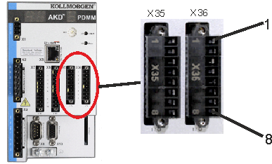
I/O connectors X35 and X36 (AKD-M only)
AKD PDMM offers two additional connectors X35 and X36 for digital I/O signals.
|
AKD-M |
|---|
|
|
|
Conn. |
Pin |
Signal |
Abbreviation |
Function |
|---|---|---|---|---|
|
X35 |
1 |
Digital Common X35 |
DCOM35 |
Common line for |
|
X35 |
2 |
Digital Input 21 |
DIGITAL-IN 21 |
Programmable |
|
X35 |
3 |
Digital Input 22 |
DIGITAL-IN 22 |
Programmable |
|
X35 |
4 |
Digital Input 23 |
DIGITAL-IN 23 |
Programmable |
|
X35 |
5 |
n.c. |
n.c. |
- |
|
X35 |
6 |
n.c. |
n.c. |
- |
|
X35 |
7 |
Digital Output 21- |
DIGITAL-OUT21- |
Programmable |
|
X35 |
8 |
Digital Output 21+ |
DIGITAL-OUT21+ |
Programmable |
|
|
||||
|
X36 |
1 |
Digital Common X36 |
DCOM36 |
Common line for |
|
X36 |
2 |
Digital Input 24 |
DIGITAL-IN 24 |
Programmable |
|
X36 |
3 |
Digital Input 25 |
DIGITAL-IN 25 |
Programmable |
|
X36 |
4 |
Digital Input 26 |
DIGITAL-IN 26 |
Programmable |
|
X36 |
5 |
n.c. |
n.c. |
- |
|
X36 |
6 |
n.c. |
n.c. |
- |
|
X36 |
7 |
Digital Output 22- |
DIGITAL-OUT22- |
Programmable |
|
X36 |
8 |
Digital Output 22+ |
DIGITAL-OUT22+ |
Programmable |
Digital common lines for X35 and X36 are not common to each other.
The DCOMx line should be connected to the 0V of the I/O supply when using sensors of type "Source" with digital inputs.
The DCOMx line should be connected to the 24V of the I/O supply when using sensors of type "Sink" with digital inputs.